Fundamental of Bit Error Rate
Bit Error Rate (BER)
- BER is the major indicator of performance of digital transmissions.
- As data is transmitted some of the bits may not be received correctly. The more bits are incorrect, the more signal will be affected.
- It is important to know what portion of the bits are in error so we can determine how much margin the system has before failure.
How bit error occurs?
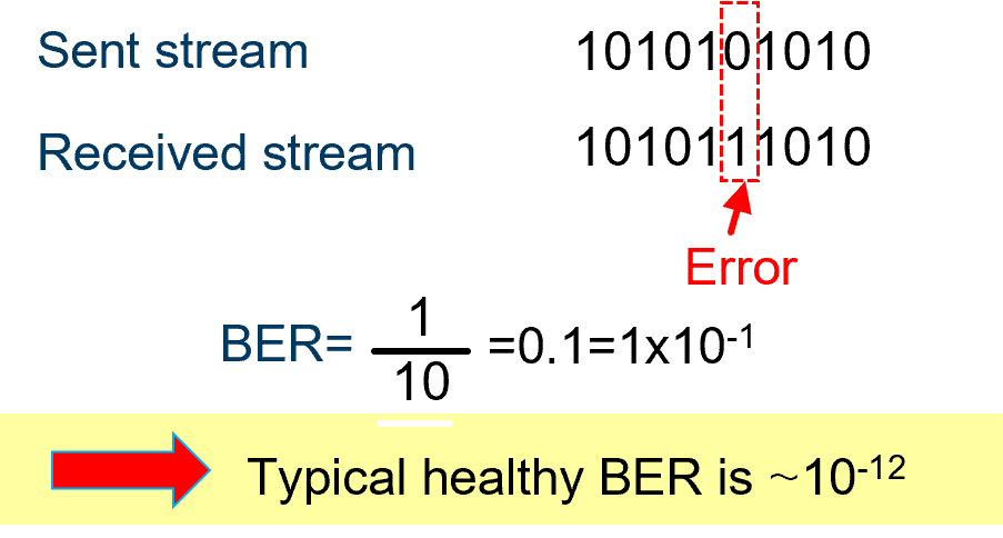
When the noise is added to the signal and the logical level cannot be properly identified:

How to calculate BER
BER is the ratio of the number of wrong bits over the total number of bits sent in a transmission.


Bit Error Rate (BER)
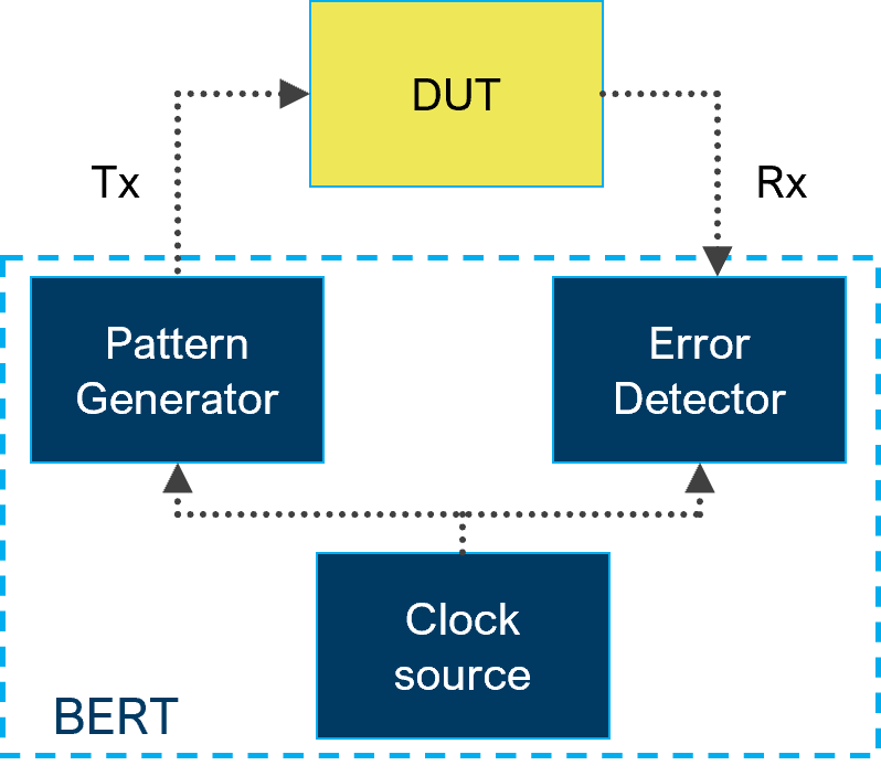
A Bit error rate tester or BERT is a device that compares the transmitted pattern with the receiver pattern, bit by bit, and computes the number of errors in this pattern. It is also called a bit analyzer.
Main components of BERT
Pattern Generator: Transmits a defined test pattern (repeatable) bit sequence) to the DUT/system/network
Error Detector: Counts the errors that occurred in transmission
- Bit error – wrong bits in the test pattern sequence
- LSB error – Least significant bit error in a pattern, e.g.: 0011 0101
- MSB error – Most significant bit error in a pattern, e.g.: 0011 0101
Clock source: Synchronizes the pattern generator and the error detector
Example of MSB and LSB for value of 149 mV:
Binary (Decimal: 149) | 1 | 0 | 0 | 1 | 0 | 1 | 0 | 1 |
Bit weight for given bit position n ( 2n ) | 27 | 26 | 25 | 24 | 23 | 22 | 21 | 20 |
Bit position label | MSB | LSB |

If error on LSB new value is 148 mV
If error on MSB new value is 21 mV
BER tester: Typical applications
BER testers are useful to:
- Stress a device or a link with continuous or burst bit traffic (User-defined or standard patterns - PRBS, SSPRQ)
- Test a new design board quality
- Validating FPGA chip performance
- Test transceiver robustness for specific bit rate and characterize the receiver sensitivity
- Troubleshoot a transmission impairment
BER testing setup transmission component
BER testing setup for transceivers


1. TOSA= Transmitter Optical Sub-Assembly
2. ROSA= Receiver Optical Sub-Assembly
3. MCB= Module Compliance Board
Types of BER testers
Unframed BERT: Generation of electrical NRZ
or PAM4 patterns to analyze the error rate
Applications: lab, production, design, verification
Device under test (DUT):
- AOC (Active Optical Cables)
- DAC (Direct Attach Copper cable)
- MCB (Module Compliance Board)
- HCB (Host Compliance Board)
- TOSA (Transmitter Optical Sub-Assembly)
- ROSA (Receiver Optical Sub-Assembly)
- Client side to the line side test
- FEC capabilities for 100G+ interfaces
- No quality-of-service testing capabilities
Electrical / Physical layer
BER tester
Protocol
BER tester
Framed BERT: Generation of NRZ or PAM4 patterns in
a protocol frame (Ethernet, OTN, Fiber Channel, etc.)
to analyzer the error rate
Applications: transport, networking, access, mobile,
data center and lab
Device under test (DUT):
- Network element
- Transceiver
- Router
- E2E network
- Data Center links
- Client side to the line side test
- FEC capabilities for 100G+ interfaces
- QoS & Networking performance testing capabilities


Forward Error Correction (FEC)
What is FEC?
FEC (Forward Error Correction) is an advanced coding technique that detects and autocorrect errors through the links
Why do we use FEC?
For 100G+ components, a healthy BER is not enough to guarantee the quality of transmission, so the IEEE defined the FEC as mandatory in the specifications for 100G & 400G Ethernet (IEEE 802.3bs task group).
Principle of FEC
FEC transforms transmitted data into code words that include redundant data. The receiver decoder uses the added redundancy to detect and correct errors that may occur in the message.
Types of FEC
The IEEE802.3bj standard specifies transmission methods using Reed Solomon FEC (RS-FEC). In this standard, 100GBase-CR4/KR4 uses RS (528, 514) and 100GBase-KP4 uses RS (544, 514).
KR4 FEC is used for NRZ coded signaling and the KP4 FEC is used in PAM4


